Draw a Technical Cutaway Poster of a Pin-Tumbler Lock
Make a 1950s shop-manual cutaway poster of a lock in Lopsy, with pattern-fill section hatching, cloned pins, a rotated face view, callouts and a parts list.
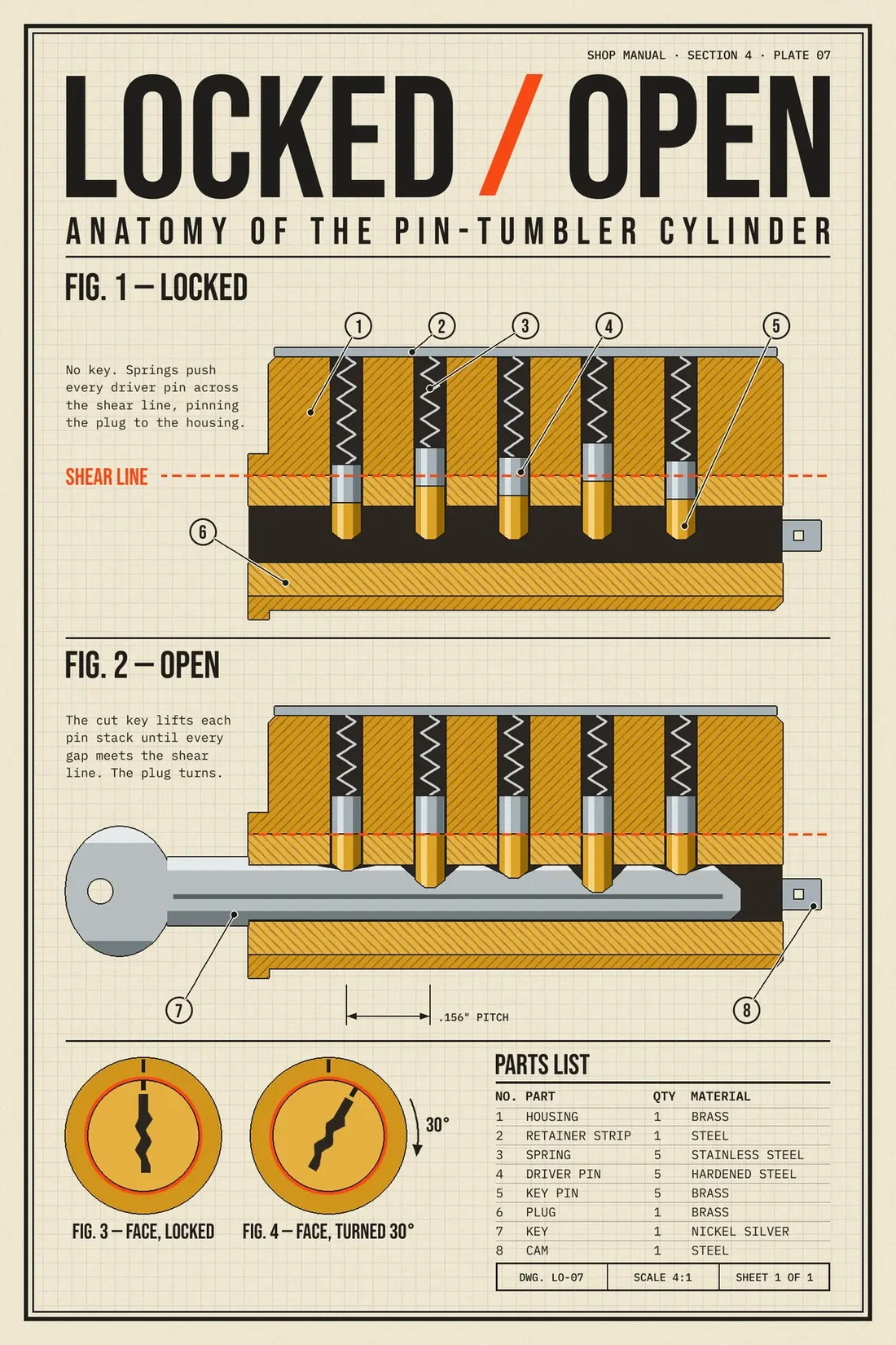
Old shop manuals explained machines with cutaways. The part is sliced down the middle, the cut metal is hatched, and every piece gets a numbered balloon. It's a great format for a poster. Here you'll draw one of the best mechanisms to explain that way: the pin-tumbler lock, shown locked and then open.
The whole idea fits in one line: the plug only turns when every gap between a key pin and a driver pin sits on the shear line. So the poster shows two sections of the same lock:
- Fig. 1, locked: with no key, the driver pins straddle the shear line.
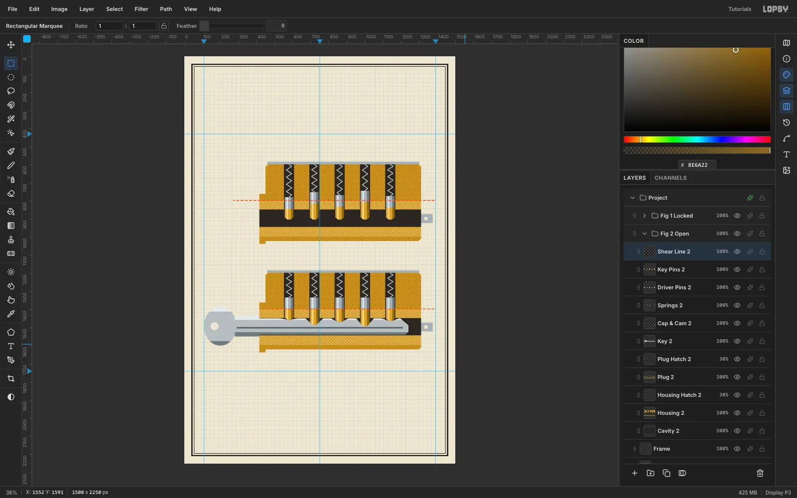
- Fig. 2, open: the right key lifts every gap onto it.
Everything is drawn from marquees, lassos and fills. There are no photos. Along the way you'll use:
- Define Pattern and Fill with Pattern (for section hatching, a dashed line and grid paper)
- the Magic Wand with Contiguous off
- copy, paste in place, Move and Merge Down to clone parts
- a ⌘-snapped rotate transform
- the Stroke effect for ink outlines and leader halos
- Grid and Snap, ruler guides and groups
- two Google fonts: Bebas Neue and IBM Plex Mono
The palette is a period brass-and-steel one, with a single accent colour:
- paper
#EDE6D3 - ink
#1F1D1A - brass
#C8973A(housing) and#DDB255(plug) - cavity
#2A2622 - steel
#6C757A/#A9B1B5/#DCE2E4 - safety orange
#E4572E, used only for the shear line
-
Set up a portrait sheet
Create a 1500 × 2250 px document (a 2:3 poster) with a White background. Set the foreground to paper
#EDE6D3, then choose Edit → Fill on Layer 1 and rename itPaper.
-
Draw the hatch, dash and grid tiles
Three repeating textures do most of the drafting work. Add a temporary layer called
Tiles, zoom in to about 600% on an empty corner, and draw them with fills:- Housing hatch: a 32 × 32 square with 3 px ink lines at 45°, one every 16 px. Lasso each diagonal band and fill it. Where a band runs off the square, it has to come back in on the opposite edge, or the tiles won't meet.
- Plug hatch: the same tile mirrored, with the lines leaning the other way. Adjacent parts in a section drawing are always hatched in opposite directions.
- Dash: a 16 × 4 orange block inside a 24 × 4 marquee. The 8 px transparent tail becomes the gap.
- Grid: a 24 × 24 square with a 1 px
#9FB4BCline along its top and left edges.
Marquee each tile exactly and choose Edit → Define Pattern. Then delete the
Tileslayer.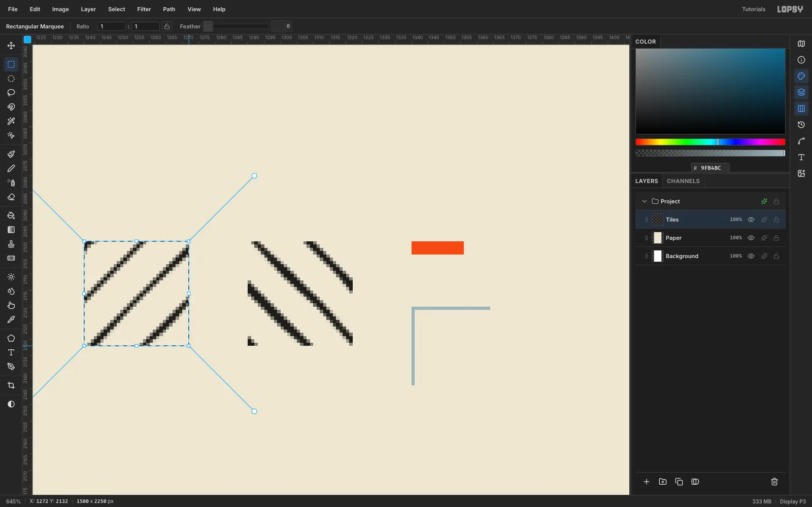
-
Tile the grid paper
Add a layer called
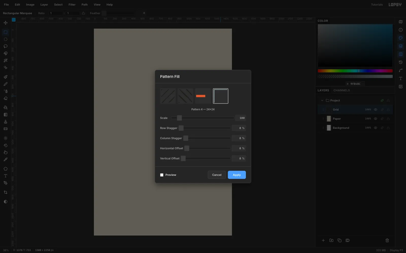
Gridabove Paper. With nothing selected, choose Edit → Fill with Pattern…, pick the grid thumbnail and click Apply. Then finish the layer:- Marquee (56, 56) → (1444, 2194), choose Select → Inverse, press Delete, then Cmd+D.
- Set the layer's Blend to Multiply (in the ✦ effects drawer).
- Set its opacity to 32%.
-
Add the border and margin guides
On a
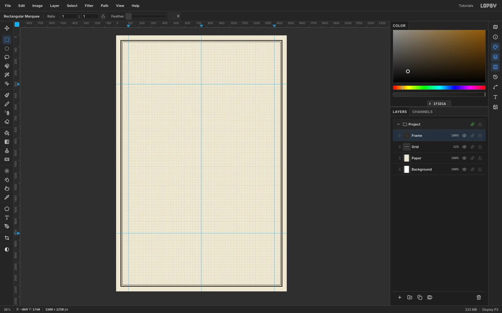
Framelayer, draw two rules. For each one, fill a marquee, run Select → Shrink… and press Delete:- an outer rule from (40, 40) to (1460, 2210), shrunk by 6
- an inner rule from (54, 54) to (1446, 2196), shrunk by 2
Then click the rulers to drop guides:
- vertical guides at x 110 and 1390 (the margins) and 750 (the centre)
- horizontal guides at y 428 (under the title) and 1740 (above the bottom band)
Everything in the poster stays between the two margin guides.
-
Cut the housing and plug
Click New Group and name it
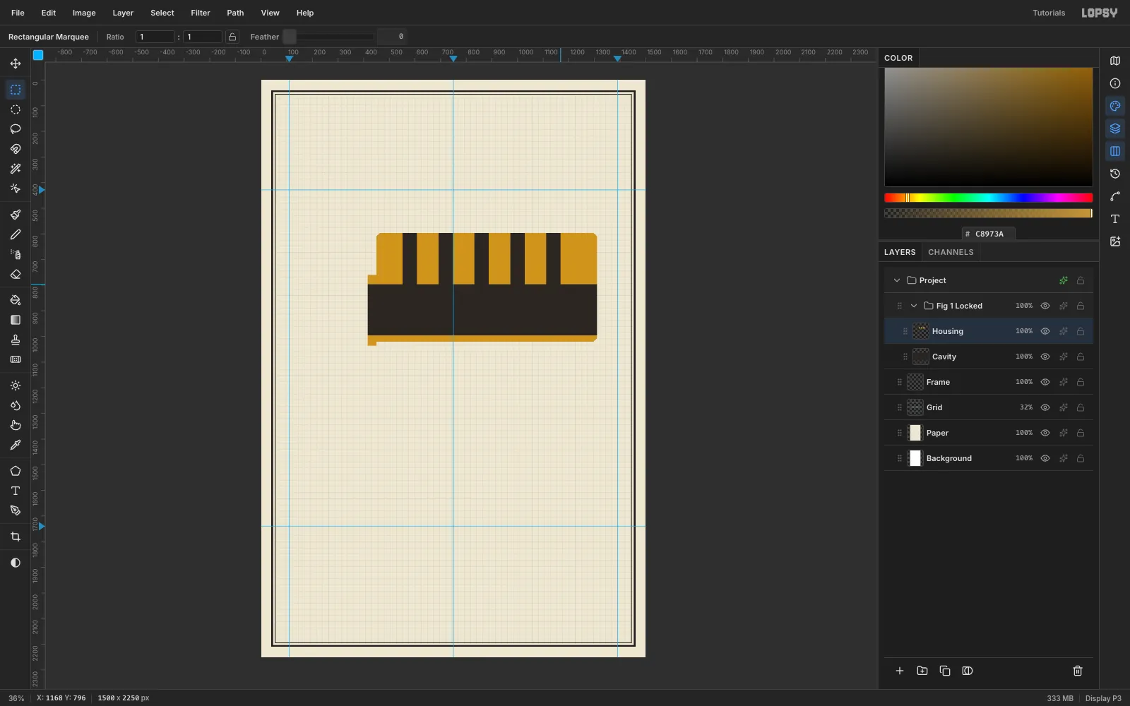
Fig 1 Locked. Build the section from the back forward, one layer per part:- Cavity: lasso the whole cylinder outline and fill it with
#2A2622. The outline is the housing, from (450, 596) to (1310, 1020) with 14 px chamfered corners, plus a front lip from (416, 760) to (450, 1036). Anything you cut out of the brass layers above will show this dark "air". - Housing: fill the same outline in brass
#C8973A. Delete the plug's space, (416, 796) → (1310, 996). Then delete five 56 px-wide pin chambers from the top edge down to y 796, centred on x 580, 720, 860, 1000 and 1140. - Plug: fill (416, 796) → (1310, 996) with
#DDB255. Delete a keyway slot from (416, 846) to (1310, 942), then five 56 px pin holes from y 796 down to the keyway. - Cap & Cam: add a steel
#A9B1B5retainer strip over the chambers, (460, 582) → (1300, 596), and a small cam tab behind the plug.
- Cavity: lasso the whole cylinder outline and fill it with
-
Select the plug with the Magic Wand
Hatching has to stop at each part's edge, so select the part first. Choose the Magic Wand, untick Contiguous, and click the housing's brass. Contiguous off matters here: the chambers split the housing into separate islands, and you want them all.
Click the Add Layer button, name the new layer
Housing Hatch, and check the marching ants are still there. The selection survives the row change. Do the same for the plug, with aPlug Hatchlayer above Plug.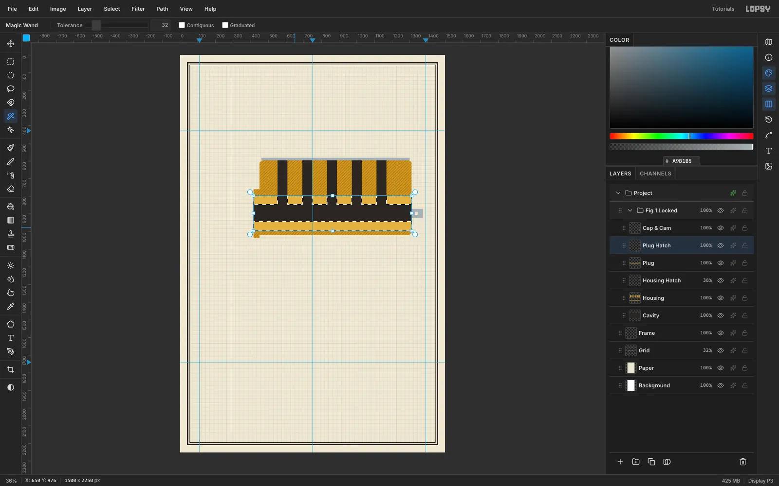
-
Fill the section hatching
With each selection live, choose Edit → Fill with Pattern…:
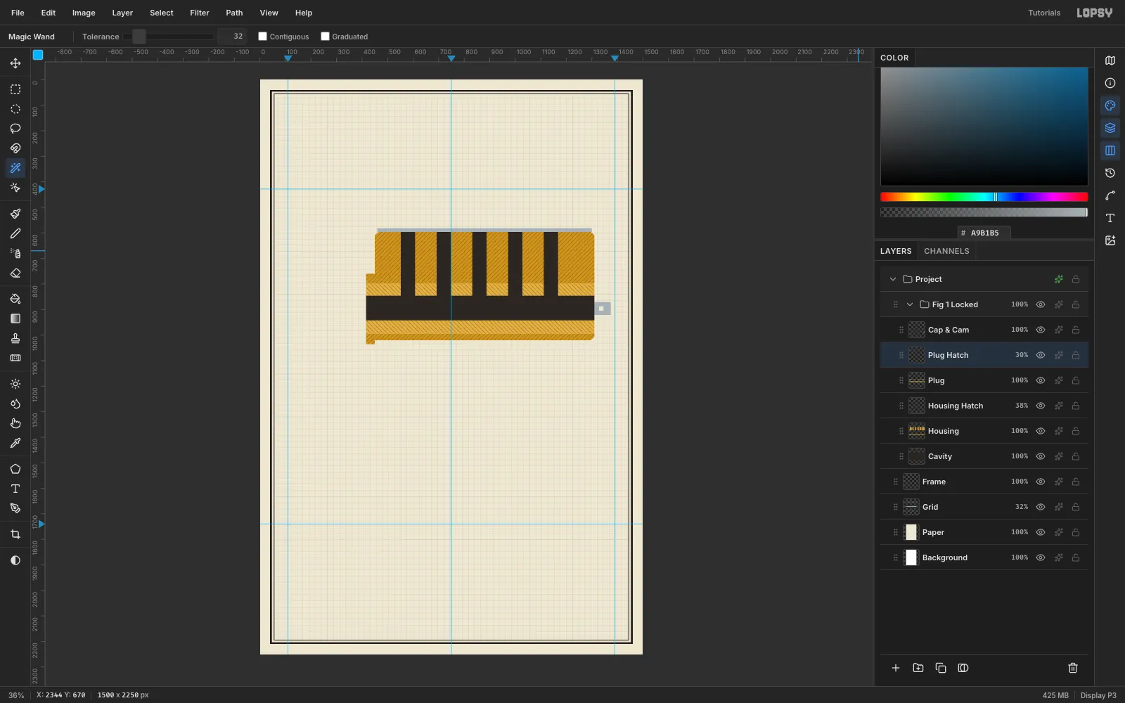
- Housing Hatch: the first hatch tile. Set Blend to Multiply and opacity to 38%.
- Plug Hatch: the mirrored tile. Set Blend to Multiply and opacity to 30%.
The pattern is anchored to the document, so the lines stay continuous across every island. Multiply lets the brass colour show through.
-
Draw the springs and the first driver pin
Add a
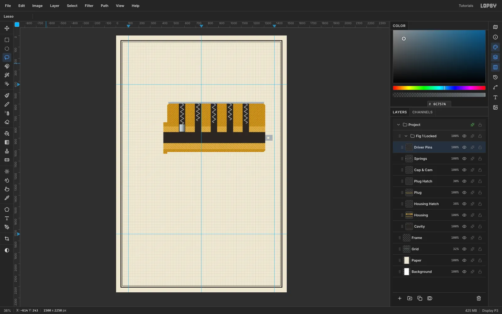
Springslayer. Pick the Brush at size 5 and hardness 100 in#C9D0D3. Drag a zigzag down each chamber, about 30 px wide with a turn every 20 px. Stop each one where its driver pin will start.On a
Driver Pinslayer, draw the first pin as a 48 × 64 rectangle in three flat tones. That's how period manuals shaded round parts:- mid
#A9B1B5for the whole pin - a 10 px light band
#DCE2E4just left of centre - a 13 px dark band
#6C757Adown the right edge
Skip gradients here. Flat bands read as printed ink.
- mid
-
Clone the pins and dash the shear line
Clone the driver pin instead of redrawing it:
- Marquee it and press Cmd+C, then Cmd+V. The paste lands in place, on a new layer.
- With the Move tool (V), drag it 140 px to the right. Use arrow keys to land it exactly.
- Choose Layer → Merge Down.
Repeat for the other chambers. In the locked view each driver sits at a different height, because it rests on a different length of key pin.
On a
Key Pinslayer, fill five brass pins in#D2A443, 60, 88, 72, 96 and 66 px long. Give each a 12 px pointed tip, a#F0D38Alight band and a#8E6A22dark band. With no key they all hang to the same depth (y 902), so their tops land at different heights, and every driver pin crosses the shear line.Finally add a
Shear Linelayer. Marquee a 4 px-tall strip along the plug's top edge, (270, 794) → (1390, 798), and fill it with the dash pattern.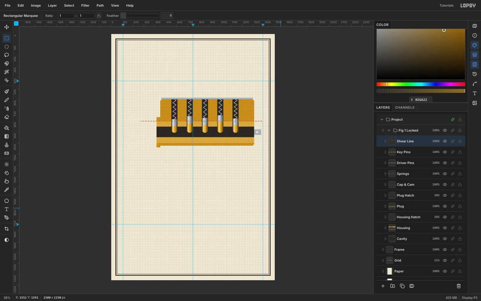
-
Insert the key
Make a second group,
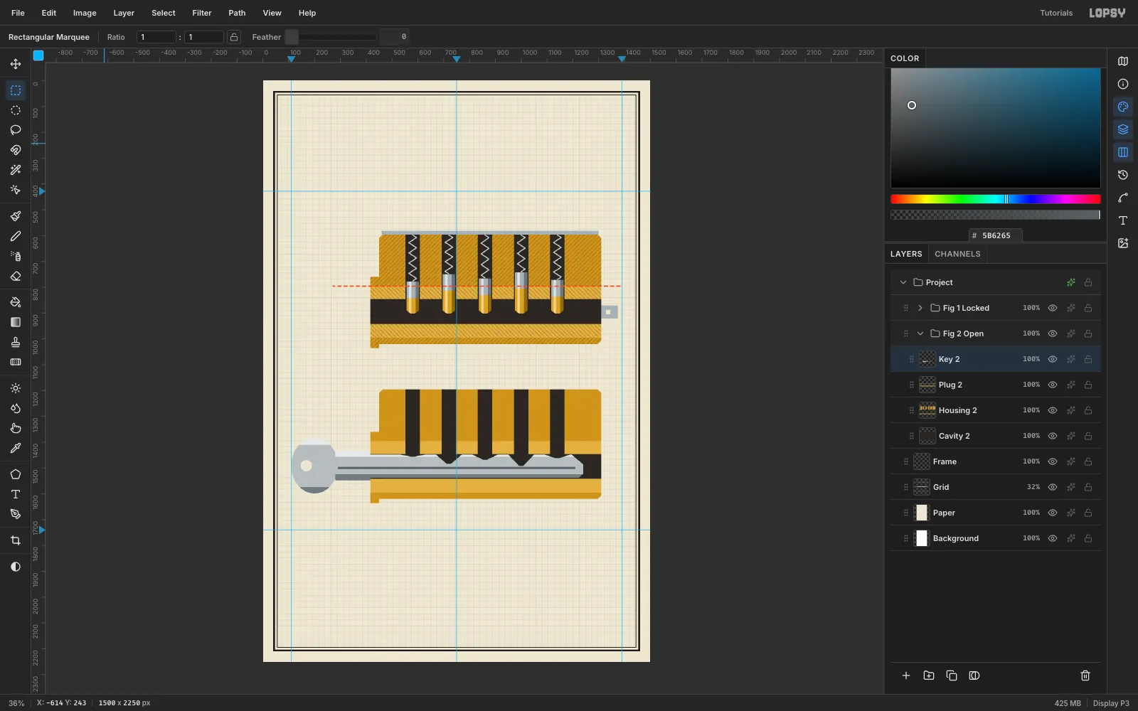
Fig 2 Open, and rebuild the housing, plug and cavity 600 px lower, using the same shapes.The key goes on its own
Key 2layer, above the plug:- Blade: fill it with nickel
#B7BDBFinside the keyway. Cut its top edge into V notches. Each notch bottom sits one key-pin length below the shear line, so the notch under the 96 px pin is the deepest. - Bow: a 90 × 108 ellipse-marquee fill outside the lock, with a 22 px hole deleted.
- Tone: add a light
#E6EAEAstrip along the top, a shadow#737B7Fstrip along the bottom and a dark warding groove#5B6265down the middle.
- Blade: fill it with nickel
-
Lift every gap to the shear line
Draw one spring and one driver pin, then clone them four times at +140 px with no vertical offset. With the key in, every driver sits at the same height.
The key pins come next. Each one's top sits exactly on the shear line, and its point rests in its notch. Add the dashed shear line across this figure too, starting at the front of the lock.
Compare the two figures: in Fig. 2, not one pin crosses the orange line. That's the whole poster.
-
Rotate the keyway 30° for the face views
In an
End Viewsgroup, draw the lock's front face twice, at (240, 1900) and (550, 1900):- a brass circle, r 130, with an ink tick at 12 o'clock
- an orange shear ring, r 99
- a lighter plug circle, r 92
On a
Keywaylayer, lasso a zigzag keyway slot and a small index notch on the left face.To turn the right face:
- Marquee a square centred on the left face, (146, 1806) → (334, 1994). Copy, paste in place and move it 310 px right.
- Re-marquee it, square and centred on that face, so the rotation pivots on the face's centre.
- With the Move tool, hold Cmd and drag the rotate handle clockwise. Cmd snaps in 15° steps, so it stops at exactly 30°.
- Press Cmd+D to commit.
Only the keyway turns. The plug's shading stays put, because light doesn't rotate with the part.
Add a black arc arrow concentric with the face (r 150) and a
30°label.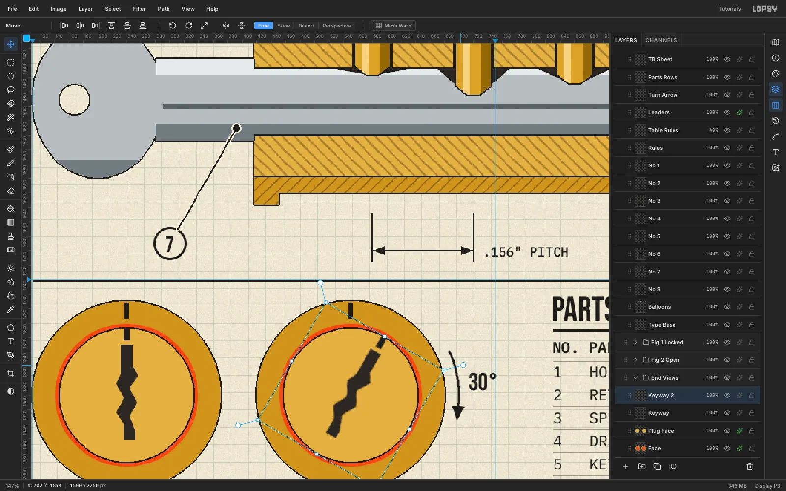
-
Set the title and track the subtitle
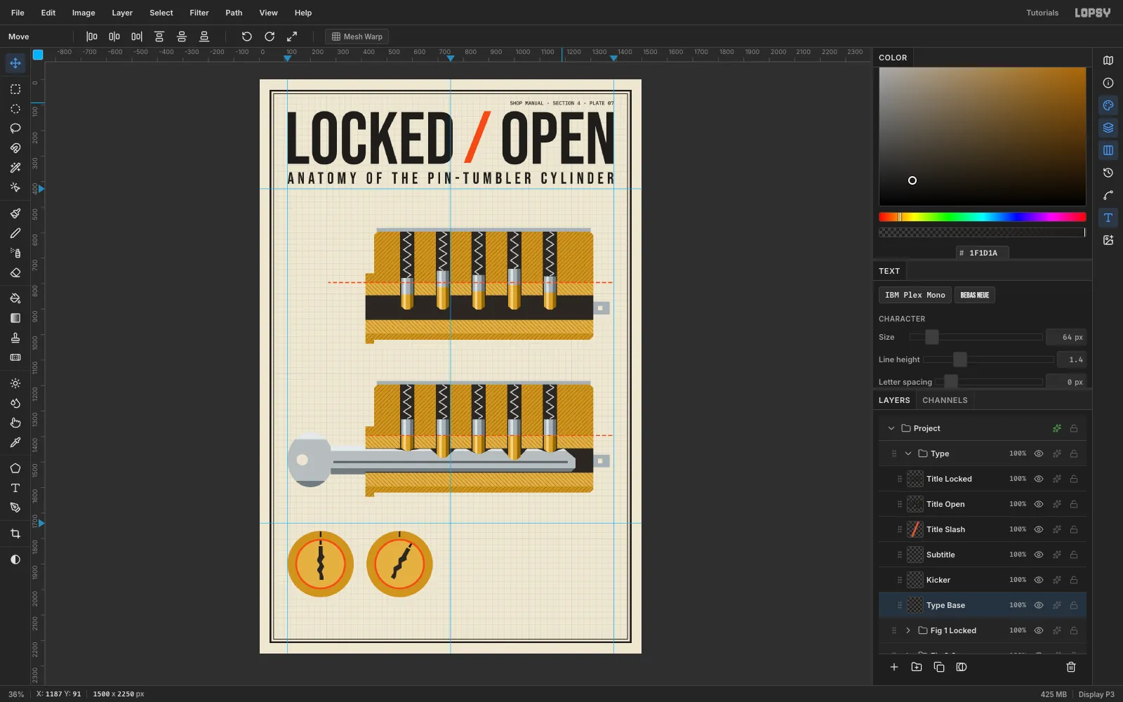
Make a
Typegroup and drag it above the figure groups. Create each text in an empty spot, then move it into place.- Title:
LOCKEDandOPENin Bebas Neue 290. PutLOCKEDflush with the left margin (x 110) andOPENflush right (x 1390), both with their tops at y 124. Centre an orange/in the gap between them. - Subtitle:
ANATOMY OF THE PIN-TUMBLER CYLINDERin Bebas Neue 64 at y 362. Then raise its Letter spacing in the Text panel until it spans exactly 110 → 1390. Here that was 14.3. - Kicker:
SHOP MANUAL · SECTION 4 · PLATE 07in IBM Plex Mono Medium 20, flush right at y 84.
- Title:
-
Add captions, notes and the parts list
Set the rest of the text in two faces only:
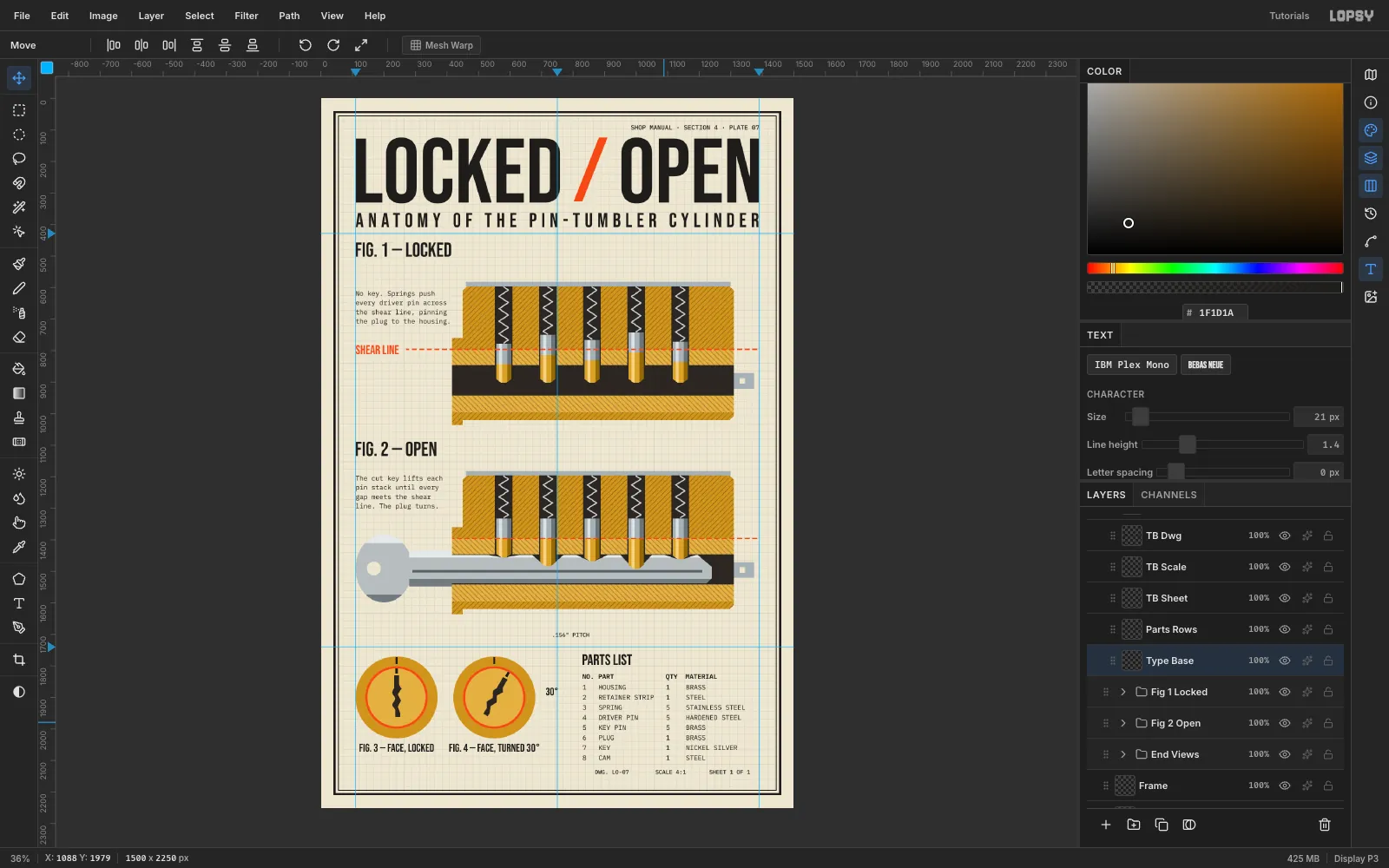
- Figure captions:
FIG. 1 — LOCKEDandFIG. 2 — OPENin Bebas Neue 64, at the left margin. - Notes: four short lines under each caption in IBM Plex Mono 21.
- Shear line label:
SHEAR LINEin orange Bebas 40, centred vertically on the dashed line. - Face captions: Bebas 36, centred under each circle.
For the parts list, use monospace columns. IBM Plex Mono has the same advance width in every weight, so spaces line up the columns exactly:
- Type a header row,
NO. PART QTY MATERIAL, in SemiBold 21. - Set Line height to 1.52 in the Text panel. Then type eight rows in Regular 21, padding every part name to the same length (e.g.
3 SPRING 5 STAINLESS STEEL).
- Figure captions:
-
Snap the heavy rule to the grid
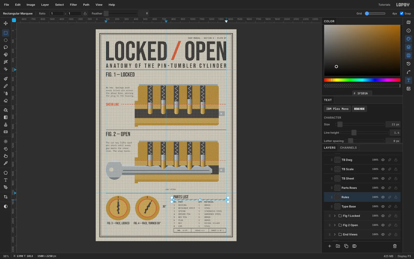
Choose View → Show Grid, set Grid to 4px in the options bar, and make sure Snap is ticked. On a
Ruleslayer, drag a marquee under the PARTS LIST heading. It snaps to a clean 560 × 4 px bar, (830, 1809) → (1390, 1813). Fill it with ink and hide the grid again.The table's other lines go on their own layers:
- Table rules: 1 px lines between the rows, on a
Table Ruleslayer at 40%. - Title block: a 2 px box from (830, 2112) to (1390, 2160), split into three cells:
DWG. LO-07,SCALE 4:1andSHEET 1 OF 1. - Band rules: full-width 3 px rules at y 428, 1066 and 1740.
- Table rules: 1 px lines between the rows, on a
-
Add balloons and leaders
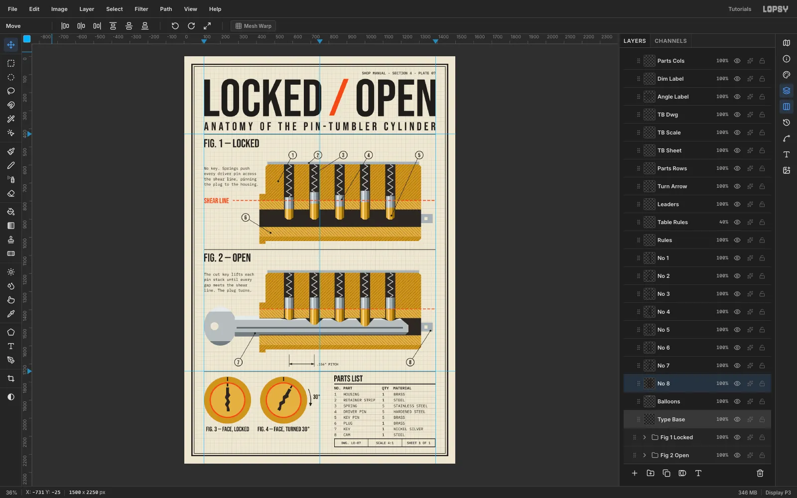
Drafting conventions to follow:
- Numbers run in reading order. Balloons 1–5 sit in a row above Fig. 1: housing, retainer strip, spring, driver pin, key pin. 6 is the plug, 7 the key and 8 the cam.
- Leaders are angled between 30° and 60°. They must never run along a spring or an edge. Each is a 3 px ink line ending in a 5 px dot on its part.
- Balloons are ink circles (r 23) with a paper centre (r 20), on a layer directly below the number text. Each number is Bebas 32, centred to the pixel.
- The pitch dimension has 2 px extension lines on the centres of pins 1 and 2, arrowheads on the line, and
.156" PITCHset outside the extension lines so it doesn't crowd them.
-
Outline the parts and finish the paper
Save the effects for last, because they make every later edit slower.
- Ink outlines: on every part layer (housing, plug, cap & cam, pins, key and faces), open ✦ and turn on Stroke: ink
#1F1D1A, Width 2, outside. - Leader halos: on the Leaders layer, add a Stroke in the paper colour instead. The halo keeps the black leaders readable where they cross the dark chambers.
- Paper grain: select Paper and run Filter → Add Noise… at Amount 12, Mono.
Export with File → Quick Export PNG, and save the
.lopsyso you can come back to it. The project reopened here pixel-for-pixel identical.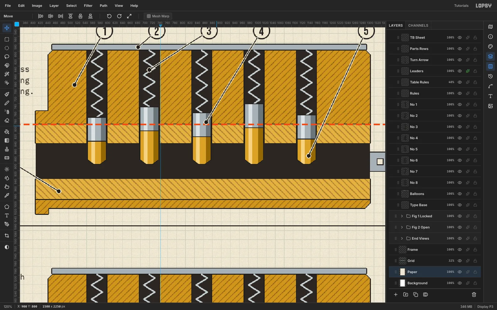
- Ink outlines: on every part layer (housing, plug, cap & cam, pins, key and faces), open ✦ and turn on Stroke: ink